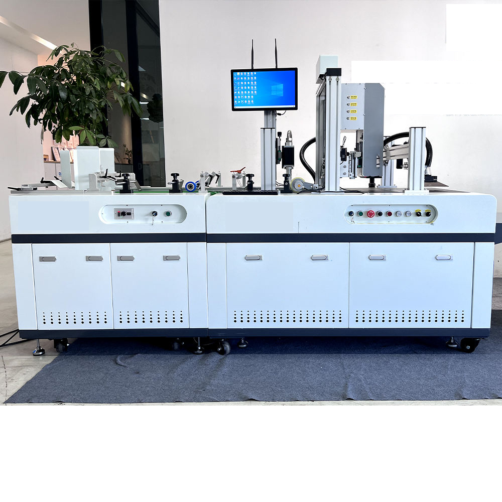
UV digital printers employ inkjet technology.
From a physical and chemical point of view the working mechanisms of the inkjet systems play an important role to the full functionality and performance of UV digital printers. No matter the curing light source or the feeding platform the device is equipped with, the final imaging quality, production speed and material adaptability are decided by how the inkjet head converts liquid UV ink into micrometer-sized ink droplets and accurately projects them onto the surface of the substrate. Thus, a thorough understanding of the inkjet principle of UV digital printers is a prerequisite for printing industry technicians to optimise process parameters, eliminate equipment failures, and improve the yield. The present article will be dedicated to the piezoelectric on-demand inkjet technology and will systematically analyse the whole physical chain from the input electrical signal to the fixation of the ink droplet.
1. Inkjet technology systems overview: The emergence of on-demand inkjet as industry mainstream
1.1 Continuous inkjet and on-demand inkjet
Inkjet printing technology can be categorised into two types, Continuous Inkjet (CIJ) and Drop on Demand (DOD). The continuous ink-jet printing ejects the ink from the nozzle with a high pressure pump and divides the jet into ink droplets by piezoelectric oscillation. Unprinted ink droplets are diverted for reuse. This method can produce ink droplets at a very high frequency (up to 1MHz), but the system is complex, the waste of ink is large, and it is impossible to realise high-precision variable ink droplet control. It is mainly used for industrial inkjet marking and not high quality image printing.
UV digital printers are typically operated in the on-demand inkjet mode, where the ink droplets are ejected only at the locati0n where the printing is needed and no ink droplets are ejected when printing is not performed. On-demand inkjet printing is of two types, thermal foaming and piezo electric. Thermal foaming – A heating resistor causes the ink to vaporise instantly , forming bubbles that expand , forcing droplets of ink out of the nozzle . However, heating can destabilise the photoinitiator in UV ink and the nozzle will have a limited life due to thermal stress. Thus, almost all industrial UV digital printers use piezoelectric on-demand inkjet technology which is also the research focus of this article.
1.2 Piezoelectric ink-jet special advantages in UV curing
Piezoelectric inkjet generates jet pressure by mechanical deformation of piezoelectric ceramics instead of heating. The non-thermal working mode guarantees that the polymer monomers, photoinitiators and pigment particles of the UV ink are not affected by heat during the spraying process and the chemical integrity of the ink formulation is maintained. The piezoelectric inkjet can also accept wider range of ink viscosity (8-30 cP, while thermal foaming usually can only accept 1-5 cP), which is the inevitable requirement for UV ink with high solid content and high colour concentration characteristics.
2. Basic physical mechanism of piezoelectric inkjet: inverse piezoelectric effect and pressure wave propagation
2.1 Engineering implementation of the inverse piezoelectric effect
The piezoelectric inkjet head works on the principle of inverse piezoelectric effect. When an electric field is applied to the polarised piezoelectric ceramic material, the crystal structure of the material is distorted to produce a mechanical strain in a certain direction. In the design of nozzles, piezoelectric elements are usually made in the form of tubes, plates or films tightly attached to the outer wall of the ink chamber or as the wall of the chamber.
The piezoelectric element deforms (contracts or expands) and thus changes the volume of the ink chamber when the driving circuit applies voltage pulses to the piezoelectric element. A sudden change of volume will generate pressure waves in the chamber and these propagate along the ink flow channel to the direction of the nozzle. Once the pressure wave reaches the meniscus (ink air interface) at the nozzle, if the wavefront pressure is sufficient to overcome the surface tension and back pressure of the ink, the ink droplet will be ejected from the nozzle. This process is analogous to shock wave propagation in an acoustic resonant cavity. The key to stable ink droplet ejection is precise control of the phase and amplitude of pressure waves.
2.2 Nozzle resonant frequency and acoustic structure
An ink flow channel (consisting of ink supply tube, chamber, flow restrictor and nozzle) is a complex acoustic resonance system. The pressure wave is reflected back and forth between the chamber and the tube that supplies the ink, and the propagation speed is determined by the sound velocity of the ink (around 1400-1500 m/s) and the geometric dimensions of the flow channel. In each nozzle design, there is an intrinsic resonant frequency (usually 20-50 kHz) and the superposition of the pressure wave is enhanced when the frequency of the driving pulse is equal to the resonant frequency, leading to the highest energy efficiency of ink droplet ejection.
In actual driving, the control system will send trapezoidal waves, bipolar waves or third-order waveforms and actively control the superposition timing of the pressure waves by adjusting the rising edge, falling edge, pulse width and amplitude of the waveform. Good waveform design can effectively suppress residual oscillations, prevent the phenomena of “satellite droplets” and “meniscus suction”, and ensure the volume, velocity, direction and height of each ink drop are consistent.
3. Process of Ink Droplet Formation: Transient Dynamics from Spray to Fracture
3.1 Four steps of ink drop ejection
The process of ink droplets ejection from the nozzle and their deposition on the substrate surface includes four physical stages:
- 1. Pressure wave generation period: The piezoelectric element deforms to generate a compression wave that propagates to the nozzle causing the meniscus to bulge outwards.
- 2. Ink column stretching phase: Under negative pressure (swelling wave) at the wavefront, the ink in the nozzle is pulled back, forming a thin liquid column (ligament).
- 3. Liquid column fracture time: The liquid column is subject to Rayleigh Prato instability under the action of the surface tension, and breaks into the main ink droplet and possibly accompanying satellite droplets.
- 4. Flight and landing time Ink droplets fly at a certain speed (usually 5-10 m/s) and reach the substrate under the action of air resistance and gravity.
3.2 Control of satellite droplets and spray stability
Satellite droplets are small companion ink droplets generated during the detachment of the main ink droplet. The volume of satellite droplets is usually 5%~20% of the main ink droplet. Too many satellite drops can cause fuzzy image edges, dirty backgrounds, or lines of QR code to get stuck. Multi-stage pulse waveforms are used in modern inkjet drivers for satellite droplet suppression. A weak reverse pulse is applied before the break-up of the liquid column to favour the break-up and contraction of the liquid column, thereby causing satellite droplets to suck back or fuse with the main ink droplet. Besides, the surface tension (generally 28-35 mN/m) and viscosity (10-25 cP) of ink are also important factors in the fracture process: high viscosity can inhibit the extension of the liquid columns and reduce the probability of satellite droplet formation, but too high viscosity can affect the response speed of ejection.
3.3 Ink droplet volume and printing in grey scale
The deformation of the piezoelectric element can be controlled by adjusting the amplitude of the driving voltage. Therefore, the volume change of the chamber changes and the volume of the ink droplet can be varied (usually 1.5-30 picoliters). UV digital printers employ this function to print grey scale . By means of a single jet to spray a variety of ink droplets of different size . They are combined to form different pixel densities , thereby achieving a smooth colour gradient . For example, when using 5-level grayscale, each pixel can be covered with 0-4 ink droplets, representing different density levels, which greatly enhances the delicacy and colour saturation of the image.
4. Inkjet head and drive system structure Integrated body for accurate manufacturing
4.1 Internal flow channel of nozzle design
Industrial ink-jet heads combine hundreds to thousands of individual nozzle channels. Each channel is made up of an ink supply port, a flow restrictor, a chamber, a piezoelectric actuator and a nozzle plate. The ink supply port is connected to the ink bag or auxiliary ink cartridge. The flow restrictor controls the resistance of ink into the chamber to ensure the timely replenishment of ink when the high-speed spraying and avoid cavitation. The chamber volume is very small (usually tens of nanoliters), and the piezoelectric actuator is fixed on the chamber wall. The nozzle plate is made of high hardness alloy or polyimide material. Circular nozzles are formed by laser drilling, and the nozzle aperture directly affects the diameter of ink droplets. Common nozzle diameters are between 20 and 50 μm.
4.2 Drive waveform and injection frequency
The driving voltage waveform is generated by a D/A converter and a high voltage amplifier, and the waveform parameters (amplitude, rise time, hold time, fall time, echo suppression section) are dynamically adjusted according to different ink types, temperature and working frequency. Modern nozzles can work at an ignition frequency of up to 80-100 kHz, which means that each nozzle can eject between 80,000 and 100,000 droplets of ink per second. At such high speeds the time for ink replenishment and pressure wave attenuation inside the chamber must be less than the ejection interval to avoid underfill or crosstalk. To this end, the ink supply system must apply a stable negative pressure (-3 to -6 kPa) to keep the meniscus in a constant position. At the same time, use a degassing device to remove the dissolved air in the ink to avoid the precipitation of bubbles under high frequency vibration.
5. Specific needs of UV ink properties for inkjet systems
5.1 Rheological parameters and adaptation for spray
UV ink consists of monomers, prepolymers, photoinitiators, pigment dispersants and additives. The viscosity of UV ink is much higher than water-based ink (~10-25 cP at room temperature for UV ink, ~2-4 cP for water-based ink). The viscosity is increased, so the energy required to overcome the flow resistance by the piezoelectric elements is increased, and therefore the driving voltage amplitude must be increased accordingly. At the same time, the thixotropy (shear thinning characteristic) of UV ink should be taken into account. The viscosity reduction at high shear rates (fast flow at the nozzle) is good for spraying, whereas the viscosity recovery at low shear rates in the chamber is necessary to keep the meniscus stable.
5.2 Temperature—A Key Parameter of Spray Stability
UV ink viscosity is very sensitive to changes in temperature, the viscosity decreases by about 2-3% with every 1℃ increase in temperature. Therefore, the industrial-grade UV digital printers are equipped with a nozzle heating system that manages the nozzle temperature within the range of 35-45°C for maintaining the ink viscosity in the optimum spraying range (8-12 cP). Furthermore, photoinitiators are sensitive to temperature, and high temperature may cause pre-polymerization, leading to nozzle clogging. Therefore, the temperature of the nozzle needs to be accurately controlled (accurate to ± 0.5 ℃), which directly affects the consistency of long-term spraying.
5.3 Pigment particle size and the risk of nozzle blockage
The pigments in UV ink are ground and dispersed. The average particle size (D50) is usually 200-500 nm. The particle size must not exceed 1/100 of the nozzle diameter (for a 30 μ μm nozzle, the maximum particle size must be ≤ 0.3 μ μm). When particles aggregate or settle, it will cause partial or full blockage of the nozzle, which will be manifested as the deviation of ink droplet, ink shortage or jet interruption. To achieve this, the UV digital printers have multi-stage filtering (1-5μm absolute precision filter at the ink inlet) in the ink path system and automatic cleaning and moisturising programmes during shutdown to prevent ink solidification at the nozzle.
6. Physical limits to inkjet printing resolution and placement accuracy
6.1 Factors Affecting Horizontal Resolution and Vertical Accuracy
The resolution of an inkjet is separated into horizontal (X direction) and vertical (Y direction). The horizontal resolution is determined by the nozzle arrangement density (number of nozzles per inch, NPI) and the micro-piezoelectric’s addressing capability. High precision nozzles can achieve 600-1200 npi and even 2400 dpi using multiple interleaved scans. The vertical resolution is defined by the accuracy of the substrate movement step and the inkjet trigger timing. UV digital printers generally use closed-loop control with a grating encoder to move the feed roller or platform in combination with high-precision linear motors to control the step error within ± 2 μm.
6.2 Sources of Deviations in Droplet Landing Position
Even in a perfect inkjet system, the position of the ink drop landing can be affected by aerodynamic interference (air vortices generated by the jets of the neighbouring nozzles), electrostatic deflection (charging of the ink droplets or static electricity of the substrate) and uneven surface energy of the substrate. So, in general, equipment of industrial grade is equipped with automatic nozzle height adjustment and corona/plasma pretreatment units to minimise the interference of environmental factors.
7. Common problems and principle analysis of inkjet system
7.1 Nozzle blockage and failure of the meniscus
Three basic reasons for nozzle clogging are evaporation of ink solvents resulting in solid content buildup, agglomeration of pigment particles and thermal precuring of photoinitiators. From the fluid mechanics point of view, the evaporation at the meniscus will increase the local concentration, form a film layer and block the nozzle. The solutions are regular ink pressing (forced ink discharge), moisturising cleaning (using a specialised cleaning solution to dissolve the solidified material) and covering the nozzle with a moisturising cap after the shutdown.
7.2 Ink drop deviation and cross-talk phenomenon
The deviation of the ink droplets is generally due to asymmetric dirt at the nozzle mouth, residual bubbles in the chamber or interference of the adjacent nozzle jet pressures. The propagation path of pressure waves may be altered by bubbles, resulting in a deviation of the injection direction. Crosstalk (mutual interference of pressure waves when adjacent nozzles spray simultaneously) can be reduced by optimising the delay of the driving waveform and physically isolating the flow channel.
7.3 Insufficient Ink Supply and Low Spray Frequency
If the ejection frequency is higher than the acoustic cut-off frequency of the ink channel, the ink replenishment speed in the chamber cannot keep pace with the ejection consumption, which can lead to the decrease of the volume of ink droplets or even leakage. At this time, it is necessary to check the back pressure of the ink supply pipeline, the degassing condition and whether the flow restrictor is blocked. If necessary, increase the pressure of the ink supply or lower the printing speed.
Summary:
UV digital printers follow the inkjet principle and are part of interdisciplinary subjects such as piezoelectric physics, fluid mechanics, acoustic resonance and materials science. From the conversion of electric field deformation of inverse piezoelectric effect to the nanosecond propagation of pressure waves in the cavity to the Rayleigh instability of ink droplet fracture, each link directly affects the accuracy, speed and reliability of the final printed product. The mastery of the inkjet principle is conducive to the reasonable setting of waveform parameters, temperature curves, and ink supply negative pressure for the technical personnel in the printing industry and can quickly diagnose the physical root causes of common faults such as clogging, deflection, and satellite droplets to maximise equipment efficiency.
From data point of view, modern industrial piezoelectric inkjet technology has succeeded in the ultra-small ink droplet control of 1.5 picoliters, the jet frequency of more than 100 kHz and the landing position accuracy of ± 3 μm . Together these indicators create an irreplaceable technological advantage of UV digital printers in such fields as labels, tags and cards. Only an in-depth understanding of the inkjet principle will allow us to truly control this precision equipment and unlock its potential on every printed product.
No responses yet