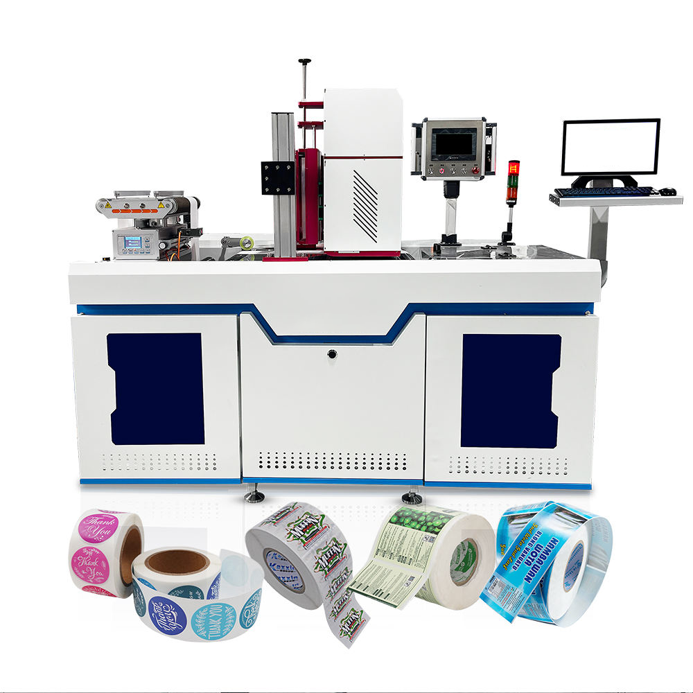
With the continuous development of digital printing technology, the quality performance of water-based digital printers is getting closer and closer to that of traditional offset printing, and water-based digital printers have become an important technical direction in label printing due to their environmental attributes. The number of water-based inkjet solutions for printing single-item labels such as clothing tags, RFID tags, tickets and cards is increasing every year. As global environmental regulations become more stringent, water-based ink can provide better colour performance and lower VOC emissions on paper and some film materials, when compared with UV or solvent-based solutions.
The technical core of water-based digital printers can be divided into three levels. The printhead architecture determines the baseline of output efficiency and accuracy of the device. Colour management technology determines the breadth and accuracy of colour reproduction. The ink supply system determines the stability and consistency of long-term operation. The article will analyse in-depth from these three dimensions to help technicians in the printing industry establish a complete technical cognitive framework.
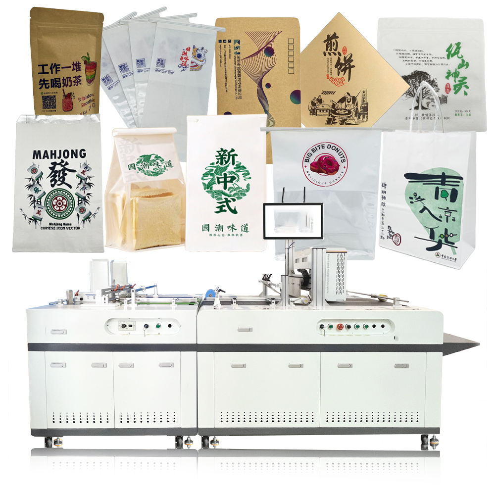
1. Working principle of single print head and scanning print head
1.1 Scanning Print Head: A precision path built line by line.
The oldest and the most widely used technological solution in the domain of digital printing is a scanning print head (sometimes called the reciprocating print head). The basic principle of operation consists in that the print head module is mounted on a carriage reciprocating along the crossbeam and the printing medium is moved in longitudinal steps. In each horizontal scan cycle, the image data is used to control the print head to eject ink droplets at the corresponding positions. Once one or more rows of pixels have been printed, the medium is moved forward one step and the head again scans in the opposite direction, repeating this process until the entire image is complete. It can be simply understood as “horizontal back-and-forth inkjet printing” and “vertical intermittent feeding”.
This scheme has naturally an advantage in precision control. Since the relative movement between the print head and the medium is divided into multiple scanning cycles, the system can calibrate the landing point position of each jet line by line and through the “overlapping scanning” technology (i.e., overlapping areas with a certain width between adjacent scanning bands), it can effectively compensate the differences in ink output and angle deviation caused by manufacturing tolerances between the nozzles. The physical accuracy of the current mainstream industrial-grade scanning print head can reach 1200DPI, and the fineness of 2400DPI can be simulated by multi-pulse grayscale technology. The production capacity of scanning printheads is however limited by the physical limits of carriage acceleration and media step speed. For example, a full colour, A3 size print job will usually take anywhere from 30 seconds to 2 minutes. This makes it difficult to cope with large continuous production runs.
1.2 Single Print Head: A One Pass Efficiency Revolution
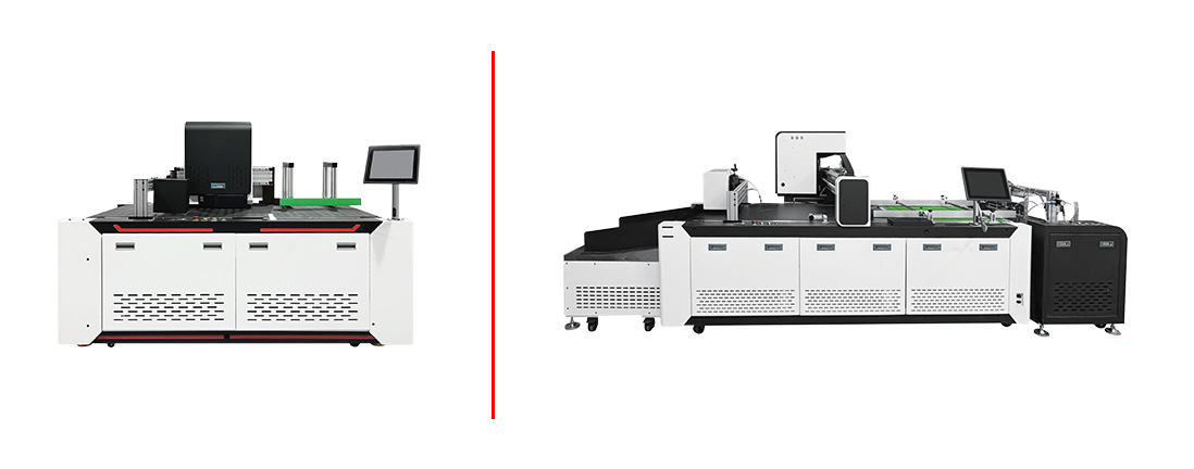
The single-pass printhead has revolutionised the traditional concept of “print head movement”. The design idea is to connect multiple print head chips in a linear way in the direction perpendicular to the movement of the medium, so as to form a fixed nozzle array covering the whole printing width. While the printing medium is moving at a constant speed through the nozzle array, all nozzles spray synchronously according to the image data, and the whole image is completed in one vertical stroke without lateral reciprocating motion.
From the physical implementation point of view, the key technical challenge of single print head is “seamless stitching”. A single nozzle chip is usually a few inches wide (Kyocera KJ4 series is about 4.25 inches for example), so multiple chips must be connected end to end to cover A3 or larger widths. White or colour lines in the junction can be directly generated by physical gaps, angular deviations and different thermal expansion coefficients between chips. Thus, the splicing error of the high-end single print head system is controlled within ± 5 μm by using a micrometer-level mechanical positioning, and a software compensation algorithm. In terms of efficiency, a single print head has a crushing advantage. The line speed of mainstream industrial equipment can reach 30-100 metres per minute, and some equipment specially designed for label rolls can even reach 150 metres per minute. The efficiency makes water-based digital printers economically competitive with flexographic and offset printing for large runs of labels, tickets and cards.
1.3 Selection logic and technical trade-offs of two architectures
Scanning and single print heads are not just a matter of “which is better or worse”. It is a branch of technology for different application scenarios. The advantage of scanning architecture is higher precision limit, lower equipment investment threshold and smaller impact of a single nozzle failure to the whole image (can be compensated by overlapping scanning). This makes it more appropriate for small batches, high added value and strict requirements for image details, such as art reproduction, high-end cosmetic labels and anti-counterfeiting QR code precision-demanding cards. The single architecture follows the core logic of “speed for cost”. When the demand for production capacity exceeds a certain threshold, the single printing cost can be reduced to 1/5 to 1/10 of the scanning type. However, the initial equipment cost and the cost of maintenance of nozzles are greatly increased, and the requirements of the flatness of material and the stability of the feeding system are higher.
For factories that produce clothing tags, RFID tags, and ticket printing, with daily output less than tens of thousands of sheets, scanning water-based digital printers is enough and more versatile. Once the daily output is in the hundreds of thousands or even millions, the efficiency advantage of a single print head will translate directly into commercial competitiveness. Note that in recent years, the nozzle manufacturers such as Epson, Kyocera and Ricoh have continuously introduced the higher-integration single-use printing modules, and the splicing accuracy and durability have been continuously improved. The single-use solution has gradually sunk into the mid-volume market.
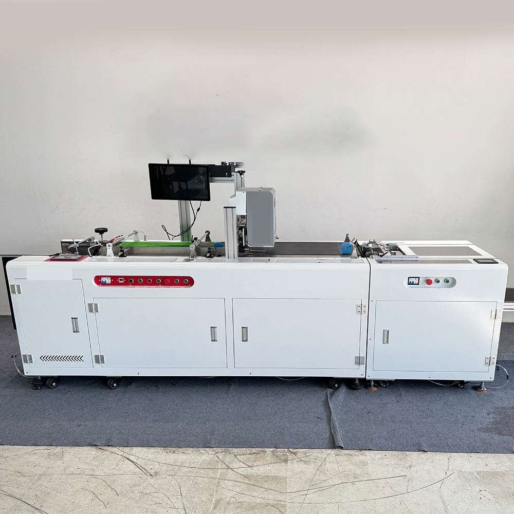
2. Multichannel CMYK Colour Management
2.1 Colour Reproduction Dimensionality Expansion: From Four Colours to Multi-Channels
Normal CMYK 4 colour printing uses the dot area ratios of cyan, magenta, yellow and black inks to simulate most colours in the visible spectrum. However, owing to the spectral properties of real pigments, the colour gamut (gamut) of four-color inks is much more limited than that visible to the human eye, especially in the bright orange, green and purple regions where there is a large deficiency. The core of multi-channel CMYK colour management technology is to add auxiliary colour channels such as light cyan (LC), light magenta (LM), orange (OR), green (GR) or purple (VT) based on the traditional four colours, so as to expand the reproducible colour range at the physical level.
Colour management is the mathematics of mapping colour spaces. The input image is usually in RGB space (such as sRGB or Adobe RGB), and the output device has its own intrinsic colour space, a multi-channel CMYK extended space. The Colour Management Engine (CMM) converts RGB values to device-related colour spaces using the Profile Connection Space (PCS) defined by the International Colour Federation (ICC). Conversion in multi-channel mode is not a simple matrix operation, but high-dimensional look-up tables (LUTs) and interpolation algorithms. For example, a 7-channel (CMYK+LC+LM+OR) device needs to map 3D RGB input to a 7D output space. And the number of LUT nodes grow exponentially, which increases the requirements on computing resources and conversion accuracy.
2.2 Practical benefits of increasing the colour gamut and matching spot colours
The practical benefit of multi-channel CMYK technology in production is a dramatic increase in Pantone colour coverage. A typical coverage of Pantone colours in the traditional four-color printing is around 70% to 80%. When adding orange, green or purple channels, the coverage can rise to above 90%, and some configurations of high-end can reach 95%. This means that water-based digital printers can print brand logo colours accurately without spot ink, saving a great deal of time on replacing ink, cleaning and blending spot colours. This advantage is directly passed on to increased production flexibility for cases such as clothing tags and RFID tags where the customer logo colour needs to be changed often.
In addition, the multi-channel architecture also allows to add “light colour channels”. Light cyan and light magenta are used not to extend the colour range boundaries but to improve the graininess and transition smoothness of highlight areas. In the single print head high speed ejection mode the volume of ink drops per pixel is generally large (e.g. 6-12 pl). Light-colored inks can reduce the colour density per unit area without reducing the physical size of the ink droplets, thereby avoiding visible dot dispersion in the highlights. Experimental data have shown that the introduction of a light colour channel can reduce the colour difference (∆∆E) between skin tone and gradient areas by 30%~40%, which is especially significant for photo-level portrait printing on tickets and cards.
2.3 Device Link: High-precision Direct Mapping Method
In conventional ICC processes, the RGB-to-multi-channel CMYK conversion involves two intermediate transformations (RGB $\to$ Lab $\to$ CMYK) that introduce quantization errors and colour gamut cropping losses. Device Link Profile technology eliminates the use of an intermediary PCS, and instead creates a mapping relationship directly from the input colour space (e.g. a specific RGB workspace) to the output device multi-channel colour space. This mapping is based on measured paired colour block data using multidimensional regression or neural network fitting. Conversion only needs one table lookup interpolation, which can reduce calculation delay and avoid colour cast accumulation caused by repeated conversion.
The benefits of Device Link in the application of water-based digital printers in label printing are reflected in two aspects. First, in high-speed printing mode, the reduced number of colour conversion steps can save RIP processing time, which is of great significance for real-time variable data printing (such as RFID coding printing). Second, for some specific brand colours, Device Link allows users to customise mapping intentions (such as absolute chromaticity or saturation priority) and perform exclusive calibration on specific material ink combinations, improving colour consistency from “batch stability” to “reproducibility across different materials and time periods”. More and more digital printing machine control systems are beginning to natively support Device Link as a standard option for high-end colour management.
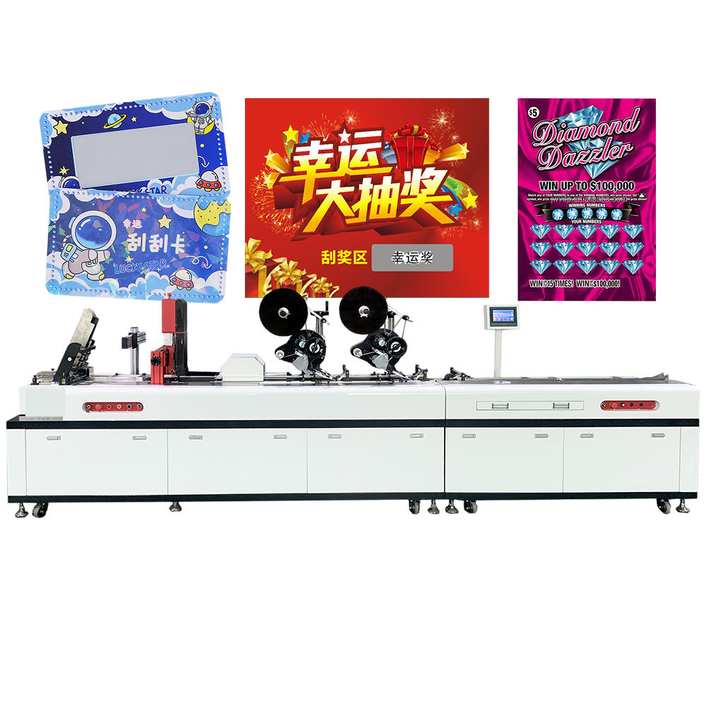
3. Negative pressure automatic ink feeding system
3.1 Basic principles and system composition of negative pressure control
The nozzle of a water-based digital printer contains highly accurate microchannels. Typically, the nozzle diameter ranges from 20 to 30 μm. The deformation of piezoelectric ceramics ejects ink droplets to produce pressure waves. However piezoelectric elements are capable of only instantaneous positive pressure. When the static pressure (i.e. static pressure) of ink in the nozzle is positive, the ink will continue to overflow by gravity or syphon effect, and form the “ink droplets”; when the negative static pressure is too high, the piezoelectric element needs to overcome a large back pressure to absorb ink, which will easily lead to ink shortage or insufficient ejection speed. Therefore, it is necessary to precisely control the static ink pressure inside the nozzle in a micronegative pressure range (generally 1-4 kPa, depending on the ink viscosity and nozzle model).
The main components of the automatic negative pressure ink supply system include main ink bottle, secondary ink cartridge (also called buffer ink cartridge), negative pressure generating device (such as vacuum pump or Venturi tube), pressure sensor, electrically controlled pressure regulating valve and connecting pipelines. The closed-loop control logic is as follows, the pressure sensor detects the real-time value of the air pressure at the inlet of the secondary ink cartridge or nozzle, feeds back the value to the controller, and compares the set value to drive the pressure-regulating valve or pump speed adjustment, so that the negative pressure is always locked in the target range. In standby mode, the system automatically switches to “maintain negative pressure” (lower negative pressure value) to maintain the stability of the nozzle meniscus and prevent it from drying up. In printing state, the system switches to “working negative pressure” for the kinetic energy consistency of ink droplet ejection.
3.2 Dynamic compensation and high speed printing adaptation mechanism
In the case of high-speed single printing, the nozzle continuously sprays a lot of ink droplets at a very high frequency (30-50 kHz), and the ink consumption near the nozzle is extremely fast. The slow response of the negative pressure ink supply system will lead to the instantaneous negative pressure fluctuation inside the nozzle , which will lead to the deviation of the ink droplet volume and velocity , and finally show the uneven density or stripes on the printed product . Advanced automatic negative pressure system adopts a “feedforward+feedback” composite control strategy. The feedforward link controls the speed of the ink supply pump in advance based on the unit time ink injection (ink consumption rate) in the print data, compensates the large flow consumption in advance. The feedback loop corrects the residual error of the feedforward by using a high-frequency pressure sensor (sampling rate ≥ 1 kHz).
Experimental results demonstrate that the nozzle pressure overshoot of water-based digital printers with high-performance automatic negative pressure systems can be controlled within ±0.2 kPa during the switch from standby state to full-width high-speed printing, and the stabilisation time is less than 0.5 seconds. The volume deviation of ink drops is reduced from ± 15% (without compensation) to ± 3%. This level of accuracy is very important for high-resolution elements such as QR codes and fine lines that are sensitive to ink volume and directly influence the barcode grade that can meet the ANSI Grade A standard.
3.3 Diagnosis of faults in the negative pressure system and daily maintenance points
While the automatic negative pressure system is very smart, printing companies still need to master the basic knowledge of fault identification. Common abnormal phenomena are: printing “white lines” (corresponding to ink breakage in a certain nozzle); ink flying on both sides of the nozzle (due to the protrusion of the meniscus caused by low negative pressure); and the overall printing colour becoming lighter (due to the insufficient spray volume caused by high negative pressure). At this stage, it is best to first check the difference between the pressure sensor reading and the actual negative pressure gauge value to rule out sensor drift; Next, check whether there are any bubbles gathering in the pipeline, as these bubbles can cause delayed pressure transmission and random fluctuations. Most of the modern digital printers with water-based ink are equipped with a “bubble self-test” programme, which detects the change of the current of the ink supply pump to identify the air content in the pipeline and automatically initiates a bubble discharge operation. Regularly changing the air filter, cleaning the secondary ink cartridge level sensor, and calibrating the negative pressure setting value (at least once every quarter) can effectively avoid more than 90% of printing defects related to ink supply.
4. FAQ – Frequently Asked Questions
Q: If you are using a single print head, will you always see a “seam” at the join? How to get rid of it?
In the ideal calibration state, modern single print heads can control the colour difference at the joint to ∆ ∆E ≤ 1.5 by micrometer-level mechanical adjustment and software edge feathering algorithms (gradually blending the overlapping areas of adjacent nozzles), which cannot be detected by human eye at normal observation distances. However note that the splicing gap will change due to the thermal expansion and contraction due to the changes in environmental temperature. High-end equipment may have automatic temperature compensation algorithms built in, or require constant temperature and humidity workshop operation.
Q.Multi-channel CMYK does not require special RIP software. Can I use normal four colour RIP?
Extended channels in multi channel CMYK require LUT conversion capability in RIP. A normal four-color RIP cannot generate seven- or eight-color separation data. At present, mainstream brands like EFI Fiery, GMG ColorServer, ColorGATE, etc. support multi-channel device profiles, and all of them can customise the channel combination. If the normal RIP is used to force the multi-channel devices, only the partial channels can be used and the colour gamut and saturation cannot be fully used.
Q: What precautions should be taken when restarting an automatic negative pressure system after a long period of shutdown?
If the machine has been shut down for more than 48 hours, it is recommended to first perform a “cleaning” or “ink pressing” operation to release some of the old ink that may have thickened inside the nozzle, and observe the negative pressure value to see if it is within the normal range. If abnormal sound of the pump occurs or the pressure value can not be stabilised for a long time, it may indicate that there are dry ink blocks in the pipeline, and manual cleaning is required. When the negative pressure system is restarted, the system will automatically extract ink. When the negative pressure is not stable, the print should not be directly, otherwise it is easy to cause large-area drawing or ink flying.
Q: the negative pressure setting of water-based ink should be adjusted in high-temperature environments?
Is it required? A. It is. With the increase of temperature, the viscosity of ink is reduced, and if the original negative pressure value is sustained, the actual volume of ink ejected will be larger. Automatic negative pressure systems are generally equipped with temperature sensors, which can dynamically adjust the negative pressure target value according to the temperature of the ink. (The absolute negative pressure value decreases by about 0.2-0.5 kPa for every 5℃ increase in temperature.) In the absence of a built-in temperature compensation, it is advisable to manually reduce the negative pressure setting during the high temperature season, and to observe the density of the printed samples on a daily basis.
Summary
The technical progressiveness of water-based digital printers is mainly reflected in the printhead architecture, colour management system and ink supply control, which are the three core systems. “Reciprocating scanning and line-by-line calibration” makes the scanning print head get to the highest resolution and edge sharpness in the current industrial field, which is suitable for small batch, high-precision label and card printing. The single print head can print at a speed of 30-150 metres per minute with “full width fixation + one-time pass”, offering a cost-effective digital solution for large-scale hanging tags and RFID tags. They are not interchangeable but are two complementary layouts depending on the production capacity thresholds and accuracy requirements.
For multi-channel CMYK colour management, the addition of auxiliary channels such as light cyan, light magenta, orange or green can increase the Pantone colour coverage of water-based digital printers from 75% of the four colours to more than 90%. Combined with Device Link direct mapping technology, the colour difference can be controlled on level of ∆ ∆E ≤ 2, which can meet the strict requirements of brand colour reproduction. While the automatic negative pressure ink supply system uses closed-loop control and dynamic feedforward compensation, reducing the volume deviation of ink droplets from ±15% to within ±3% at high-speed spraying, directly guaranteeing the level stability of QR code printing and the consistency of continuous production of long orders.
From the data of the testing agencies of the industry, the failure shutdown rate of the water-based digital printer with the above three technologies is less than 2%, and the qualified rate of the product (tested by the ISO 15416 barcode verification standard) can reach more than 98.7% in the case of 8 hours of continuous operation per day. The global label printing market is expected to grow at a CAGR of 5.2% between 2025 and 2030, and the adoption of water-based digital solutions in clothing tags and RFID tags is expected to increase from 12% today to 28% by 2030. With continuous advancements in technology, digital water-based printers are capable of approaching or surpassing the speed, precision and colour spectrum of traditional printing methods, offering printing enterprises more sustainable production tools. For practitioners, a complete knowledge of the physical principles and control logic of these core technologies is the basis for scientific selection, efficient production and quick troubleshooting, and the key to building technological barriers in fierce market competition.

No responses yet